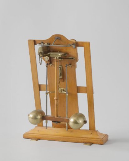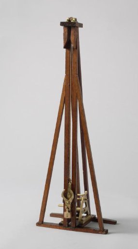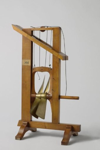
Model of a Lifting Screw
From the collection of Rijksmuseum, Amsterdam. Free to download, adapt and use — no permission needed.
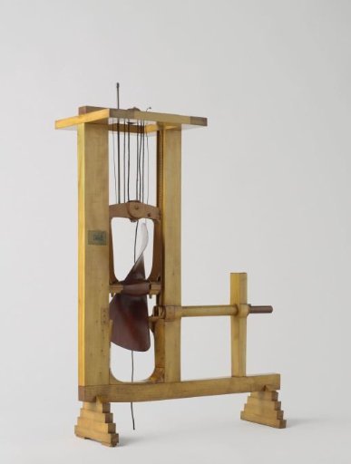
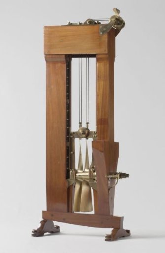
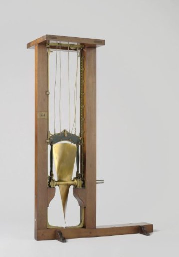
Model of a screw casing between the sternpost and the rudderpost, with a section of the keel and the sternpost. The screw lifting device consists of a loose frame with a screw, which can be raised and lowered in the casing by a rope running over a pulley at the top of the screw casing and a pulley in the screw frame. The screw is a Mangin screw, a four-bladed propeller, composed of two two-bladed screws that can be set in parallel for lifting. For this, the shaft of the rear screw, which runs through the shaft of the front screw, is provided at the back with a slot that must be set in a vertical position to lift the screw; the rail over which the slot runs immediately locks the screw in the vertical position. The front screw is then in a horizontal position. The screw shaft of this has two crossing slots at the front, which fit over the same rail: halfway, between lines A and B, this rail is interrupted, so that the screw can be rotated here.
Rijksmuseum, Amsterdam’s own description